TRANSMAG-2D
![]()
The software is used for calculation of coupled problem that consist of axisymmetrical non-linear magnetic field calculation and electrical circuit calculation.
Coupled transient 2D finite element method and mesh current method are used for solving a wide range of the problems concerned to power transformers:
|
Calculation

Calculation types
Toolbar “Calculation” is intended for input of the calculation parameters (Figure.4.1-1), and for view and analysis of results (Figure.4.1-2).
Three types of calculations are used in the program:
1. М – Transient process. In this type of calculation the program calculates own and mutual inductances of the windings by means of finite-element method, forms and solves equivalent circuit task by mesh-current method. This type of calculation usually requires less time for solving the task but ignores non-linear properties of material of the magnetic system leg.
2. F – Transient process. In this type of calculation the program solves coupled task by the finite-element and mesh-current methods. The present type of calculation permits to consider non-linear properties of material of the magnetic system leg but it requires more time for solution.
3. Harmonic. The program solves linear quasistatic task by coupled finite-element method and mesh-current method.
Calculation results
Calculation results are given in a form of Tables (Fig.4.2) and graphs (Fig.4.3). Calculation results are currents and voltages on the scheme elements, decomposition of currents and voltages into harmonic components, relationships between harmonic components and time. During harmonic calculation the program calculates reactive and active resistances (impedances) of the windings.
Calculation results can be saved in Microsoft Office Word, Microsoft Office Word Excel, Adobe Reader (*.pdf).

The program permits to superimpose graphs, to scale graphs for convenient comparison, to measure different parameters of graphs using various tools (Fig. 4.4). Besides the program permits to decompose any part of signal into harmonic components (Fig. 4.5), to create relationships between separately selected harmonic components and time and to plot a master graph with any number of harmonics (Fig. 4.6, 4.7).
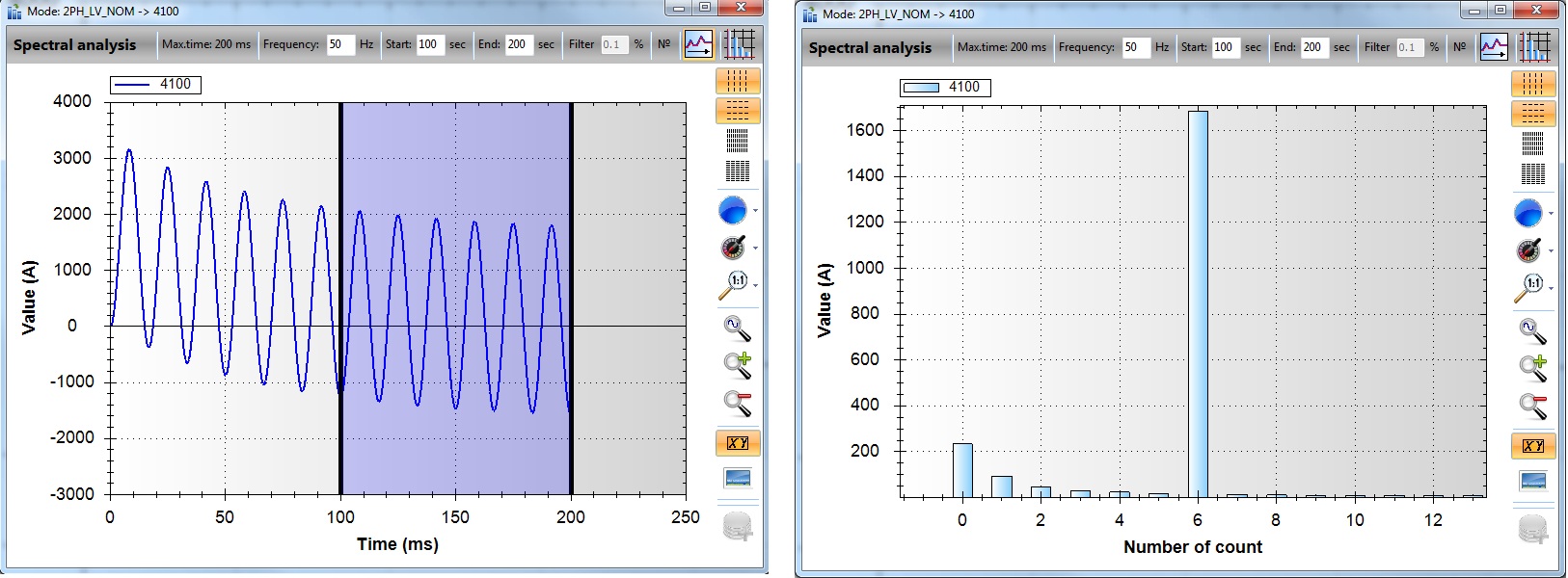

Analysis result: [fourth harmonic]

Analysis result: [zero harmonic]

Common view of the A phase model in TRANSMAG-2D software

Connection diagram of the windings and thyristor bridges in TRANSMAG-2D software

HV busing current curves

HV windings current curves

Y-valve winding parallels current curves

Total current of Y-valve winding curve, peak and RMS values of current

250 Hz component magnetic field distribution
